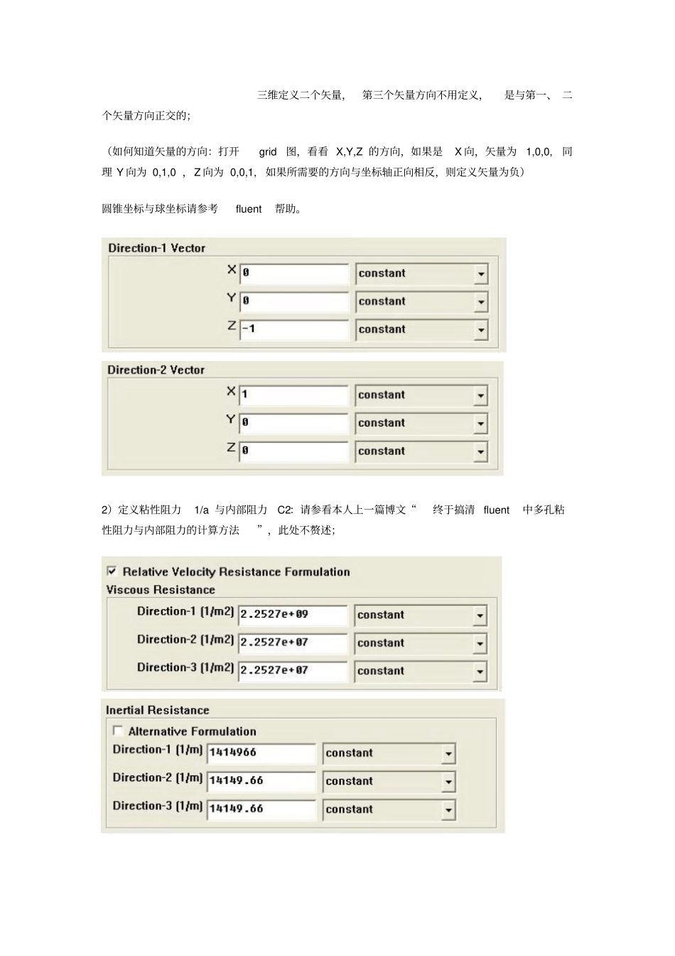
经过痛苦的一段经历,终于将局部问题真相大白,为了使保位同仁不再经过我之痛苦,现在将本人多孔介质经验公布如下,希望各位能加精:1。Gambit 中划分网格之后, 定义需要做为多孔介质的区域为fluid,与缺省的 fluid分别开来,再定义其名称,我习惯将名称定义为porous; 2。在 fluent中定义边界条件define-boundary condition-porous(刚定义的名称 ) ,将其设置边界条件为fluid,点击 set 按钮即弹出与fluid边界条件一样的对话框,选中porous zone 与 laminar复选框 , 再点击 porous zone标签即出现一个带有滚动条的界面;3。porous zone设置方法:1)定义矢量:二维定义一个矢量,第二个矢量方向不用定义,是与第一个矢量方向正交的;三维定义二个矢量,第三个矢量方向不用定义,是与第一、 二个矢量方向正交的;(如何知道矢量的方向:打开grid图,看看 X,Y,Z 的方向,如果是X 向,矢量为1,0,0,同理 Y 向为 0,1,0 ,Z 向为 0,0,1,如果所需要的方向与坐标轴正向相反,则定义矢量为负)圆锥坐标与球坐标请参考fluent帮助。2)定义粘性阻力1/a 与内部阻力C2:请参看本人上一篇博文“终于搞清 fluent中多孔粘性阻力与内部阻力的计算方法”,此处不赘述;3)如果了定义粘性阻力1/a 与内部阻力C2,就不用定义C1 与 C0,因为这是两种不同的定义方法, C1与 C0只在幂率模型中出现,该处保持默认就行了;4)定义孔隙率porousity,默认值 1 表示全开放,此值按实验测值填写即可。完了,其他设置与普通k-e 或 RSM相同。总结一下,与君共享! Tutorial 7. Modeling Flow Through Porous Media Introduction Many industrial applications involve the modeling of flow through porous media, such as filters, catalyst beds, and packing. This tutorial illustrates how to set up and solve a problem involving gas flow through porous media. The industrial problem solved here involves gas flow through a catalytic converter. Catalytic converters are commonly used to purify emissions from gasoline and diesel engines by converting environmentally hazardous exhaust emissions to acceptable substances. Examples of such emissions include carbon monoxide (CO), nitrogen oxides (NOx), and unbur...